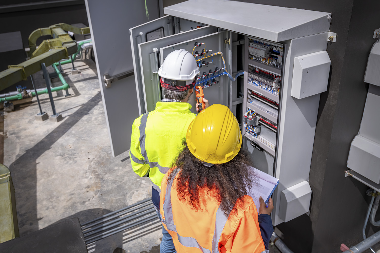
Three Phase Testing is a critical process in electrical engineering and power systems, aimed at ensuring the reliability, safety, and efficiency of three-phase electrical systems, which are widely used in industrial and commercial applications. Three-phase power is preferred over single-phase power for its ability to deliver more power with greater efficiency, but it also requires thorough testing to detect faults, verify system performance, and ensure that the system operates within specified parameters.
In a three-phase system, electricity is delivered through three alternating currents (AC) that are 120 degrees out of phase with each other. This design provides a more stable and continuous power flow compared to single-phase systems, making it ideal for heavy machinery, motors, and large electrical grids. Each phase works independently, so if one phase fails, the other two can continue to supply power, though with reduced efficiency. The phases are labeled as Phase A, Phase B, and Phase C, and the system can be configured in two ways: Star (Wye) or Delta.
Star (Wye) Configuration: In this setup, one end of each phase is connected to a common neutral point, and the other ends are connected to the load.
Delta Configuration: Here, the ends of the phases are connected in a closed loop, with each phase connected to the next.
Three-phase testing is essential for evaluating the functionality and health of electrical systems. Identifying issues such as short circuits, open circuits, or imbalances in the phases. Ensuring that the electrical load is distributed evenly across the three phases to prevent overloading and inefficiencies. Confirming that the system operates according to its design specifications under different loads and conditions. Preventing electrical hazards like overheating, fires, or equipment damage due to faults in the system.
Types of Three-Phase Tests
Insulation Resistance Testing: This test checks the insulation between the conductors and the ground, ensuring there is no leakage of current. A megger (insulation resistance tester) is typically used, applying high voltage to the system to measure the resistance. A low resistance value indicates that the insulation has deteriorated, which can lead to short circuits or faults.
Continuity Testing: This test ensures that there is a continuous path for electrical current in each phase. Any break in continuity can cause malfunction or inefficiency. Continuity testing is typically performed with a multimeter or continuity tester.
Phase Sequence Testing: Phase sequence refers to the order in which the phases reach their peak values. Incorrect phase sequencing can cause motors to run in reverse or malfunction. A phase sequence tester is used to verify the correct order of phases (A, B, C).
Voltage and Current Testing: This involves measuring the voltage and current in each phase to ensure they are within the acceptable range. Voltage imbalance or current fluctuations can lead to inefficient operation or damage to equipment.
Harmonics Testing: Harmonics are unwanted frequencies that can distort the waveform of the electrical supply, leading to inefficiencies and potential damage. Harmonics testing helps identify the presence of these frequencies and ensure the system operates smoothly.
Load Testing: This test involves applying different loads to the system to assess its performance under real-world conditions. It helps in determining the system’s ability to handle maximum loads without failure.
In conclusion, three-phase testing is essential for maintaining the efficiency, reliability, and safety of electrical systems. Regular testing helps identify issues before they become critical, ensuring that the system operates at its best.


 How To
Comments are closed